 黑客技术
点击放大
ESP32-BlueJammer - The ESP32-BlueJammer (Bluetooth jammer, BLE jammer

项目说明
<h1 align="center">ESP32-BlueJammer - by </h1>
<di="center">
<img src=" alt="ESP32-BlueJammer">
<h3 align="center">Jamming is ILLEGAL! Educational purposes only!</h3>
<h3 align="center"><a href=" <a href=" & <a href=" for Flipper Zero</a> released!</h3>
</div>
<di="center">
<a href=" title="Go to GitHub repo">
<img src=" alt="EmenstaNougat - ESP32-BlueJammer">
</a>
<a href="
<img src=" alt="stars - ESP32-BlueJammer">
</a>
<a href="
<img src=" alt="forks - ESP32-BlueJammer">
</a>
</div>
<h4 align="center">
<a href=" your own</a>
<span> | </span>
<a href="
<span> | </span>
<a href=" layout</a>
<span> | </span>
<a href="
<span> | </span>
<a href="
<span> | </span>
<a href="
<span> | </span>
<a href="
<span> | </span>
<a href=" case</a>
<span> | </span>
<a href="
<span> | </span>
<a href=" me</a>
<span> | </span>
<a href="
</h4>
ESP32-BlueJammer
The ESP32-BlueJammer (Bluetooth jammer, BLE jammer, WiFi jammer, RC jammer) disrupts devices using an ESP32 and nRF24 modules, causing plenty of noise and sending unnecessary packets (DoS).
It interrupts:
The whole 2.4GHz broadband! E that works on 2.4GHz is being interfered, like:
audio in speakers being transmitted o, microphones on 2.4GHz, smartphone connections, WiFi, RC Drones (etc.), IoT devices, smart gadgets, wireless keyboard & mouse, just anything on 2.4GHz!
Ideal for controlled disruption and security testing. Based on 2.4GHz communication.
It has a big range (o+ - may vary on your antenna and hardware setup!) on newest Bluetooth with casual 2.4GHz antennas, you can easily increase this as well by taking some simple "bigger" router antennas.
An amplifier (2.4GHz) may be a good option too!
Remember that jamming is illegal and should not be used with malicious intent!
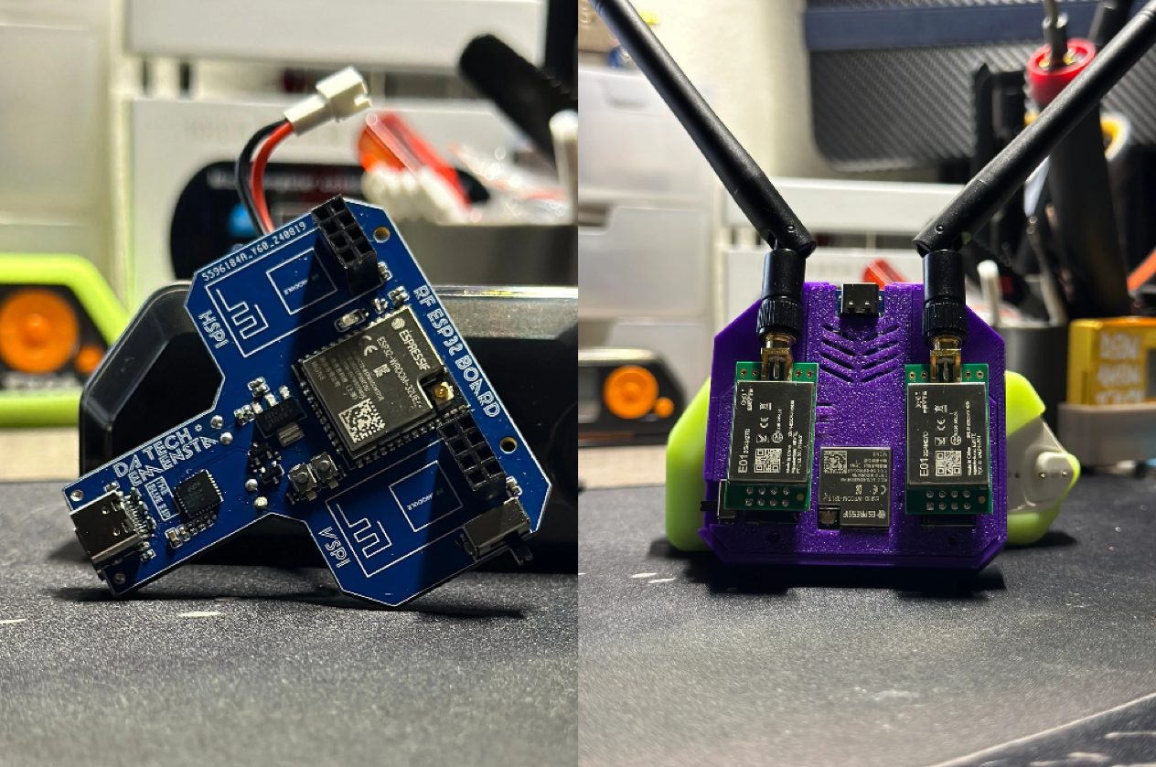
PCB's with ESP32 and RF-module capability
ESP32-RF DIY-PCB:
This PCB can fit an ESP32-wroom-32U/E DevKitC and 2 nRF-modules, along with an 0.96" I2C OLED, LEDs and switches.
*Remember: It is not intended for illegal use!*
For this one, all you need is listed below:
Required:
Additional:
!image
Shop
---
PRE-SOLDERED: "The Blue ESP"
This is an ESP32 with RF-module breakouts (nRF24/CC1101 etc.) for experimenting.
*Remember: It is not intended for illegal use, neither for my project!*
Required:
Why do you need to get the nRF24's? -> the pinout can be used to connect either nRF24 or CC1101 modules for further experiments with an ESP32 chip.
!TheBlueESP
Shop
Video tutorials and demonstrations
Full DIY assembling video tutorial
Full DIY assembling video tutorial (if the TikTok is not a for you)
---
Demonstration
Demonstration (if the TikTok is not a for you)
---
Flashing process
Flashing process (if the TikTok is not a for you)
---
ESP32-BlueJammer tutorial by
![ESP32-BlueJammer tutorial by ]()
---
Operation Channels
Frequency Range: 2.402 GHz to 2.480 GHz
Channel Width: 1 MHz
Frequency Range: 2.400 GHz to 2.4835 GHz
Channel Width: 2 MHz
Frequency Range: 2.400 GHz to 2.4835 GHz
Channel Width: Typically 20 MHz, but can be 22 MHz or 40 MHz in some cases
Frequency Range: 2.400 GHz to 2.525 GHz
Channel Width: 1 MHz
How to use?
To disrupt channels on the 2.4GHz band, do the following to enable your ESP32-BlueJammer:
Combo-Channel-Select_BT-BLE-WiFi-RC firmware:
1 blink = BT
2 blinks = BLE
3 blinks = WiFi
4 blinks = RC
State 1: Bluetooth
State 2: Bluetooth Low Energy
State 3: WiFi
State 4: RC
all other firmware:
Bluetooth_80_CH - jams classic Bluetooth
Frequency Range: 2.402 GHz to 2.480 GHz
BluetoothLowEnergy_40_CH - jams Bluetooth Low Energy
Frequency Range: 2.400 GHz to 2.4835 GHz
Bluetooth-BluetoothLowEnergy_40-80_CH - jams classic Bluetooth & Bluetooth Low Energy
Frequency Range: 2.402 GHz to 2.480 GHz & 2.400 GHz to 2.4835 GHz
Bluetooth-WiFi_14-80_CH - jams classic Bluetooth & WiFi
Frequency Range: 2.402 GHz to 2.480 GHz & 2.400 GHz to 2.4835 GHz
WiFi_14_CH - jams WiFi
Frequency Range: 2.400 GHz to 2.4835 GHz
2.4GHzRemoteControl(Drones etc.)_1-125_CH - jams RC (Drones etc.)
Frequency Range: 2.400 GHz to 2.525 GHz
Hardware - Make your own ESP32-BlueJammer
(Aliexpress affiliate links to support me-linked to the item names)
Required:
Additional:
If you're looking to add a battery:
To screw the 3D printed case together you must have:
Get this M3 kit instead:
Antennas
A frequently asked question is whether the antennas are needed and what the third antenna is for, here is the answer:
Yes, you need at least both antennas for the nRF24's! Why? To have it working on a decent range!
The a range with standard known chinese 2.4GHz antennas is about 20-30meters. Upgrading those antennas will help a lot with getting more range!
2 antennas are for the HSPI and VSPI nRF24 modules!
The 3rd antenna is plugged to the ESP32 chip itself, whether via IPEX or soldered onto its own antenna, if your ESP32 does not provide any option to add that one, it ob won't be possible!
What is the 3rd antenna used for? The third antenna connected to the ESP32 chip itself helps with reliable long-range interference. It ensures a better intermediate signal and stability when jamming!
(The third antenna is your own decision and therefore optional!)
Flashing the firmware
(Easy)
!ESP32-BlueJammerFlasher
I' a webflasher to make it super easy for you to flash your ESP32 chip with the ESP32-BlueJammer firmware of your choice!
Flashing ESP32 files (Ad)
If your ESP32 is not showing up in the device list or won't get recognized you will need to have THESE DRIVERS INSTALLED which can be found on my Discord 服务端 too!
ESP32-nRF24L01+ pinout + battery mod
Here are both pinouts for HSPI and VSPI. You need both nRF24L01 modules connected in order to achieve full capability of the device.
nRF24L01+ pinout
HSPI
| 1st nRF24L01 module Pin | HSPI Pin (ESP32) | 10uf capacitor |
|---------------|------------------|--------------------|
| VCC | 3.3V | (+) capacitor |
| GND | GND | (-) capacitor |
| CE | GPIO 16 |
| CSN | GPIO 15 |
| SCK | GPIO 14 |
| MOSI | GPIO 13 |
| MISO | GPIO 12 |
| IRQ | |
VSPI
| 2nd nRF24L01 module Pin | VSPI Pin (ESP32) | 10uf capacitor |
|---------------|------------------|--------------------|
| VCC | 3.3V | (+) capacitor |
| GND | GND | (-) capacitor |
| CE | GPIO 22 |
| CSN | GPIO 21 |
| SCK | GPIO 18 |
| MOSI | GPIO 23 |
| MISO | GPIO 19 |
| IRQ | |
Status LED
| ESP32 | 4.7k Ohm Resistor | 3mm Status LED (blue)|
|-------|-------------------|----------------------|
| GND | | (-) LED |
| | Resistor | (+) LED |
|GPIO27 | Resistor | |
OLED Display I2C (additional - make sure to use the correct firmware!)
| 0.96" OLED Display I2C | ESP32 |
|------------------------|-------|
| GND | GND |
| VCC | 3.3V |
| SCL |GPIO 5 |
| SDA |GPIO 4 |
Battery modification (additional)
| 3.7 battery | JST-PH2 connector | TP4056 Charging Module | Mini Slide Switch | ESP32 |
|---------------------|----------------------|------------------------|-------------------|-------|
| (+) Battery | (+) JST-PH2 | Bat + | | |
| (-) Battery | (-) JST-PH2 | Bat - | | |
| | | OUT + | Switch in | |
| | | OUT - | | GND |
| | | | Switch out | 3V3 |
PCB
<h3 align="center">That's how the components are placed (PCB size=7cm x 5.5cm - Larger sizes will NOT fit in the case!)</h3>
!DIYPCB
3D printed case
#### The 3D printed case fits ONLY a PCB size of 7cm x 5.5cm and you'll need to drill out 2 holes according for the M3 screws to fit through the PCB!
<h3 align="center">Access to the ESP32 micro-USB port, as well as to both EN & Boot buttons</h3>
!ESP32MicroUSB
<h3 align="center">TP4056 charging port access with charging state indicator holes (red=charging - blue=fully charged)</h3>
!USB_C_chargerWithIndicators
<h3 align="center">On/off switch with blue indicator LED</h3>
!OnOffSwitch
3D model view [download .stl]
<h3 align="center">Here's a look at the V3 2 antenna itself</h3>
!3DCaseView
3D model view [download .stl]
<h3 align="center">Here's a look at the V4 3 antenna itself</h3>
!3DCaseView
About the ESP32-BlueJammer and my 源码 代码
Yes! My ESP32 BlueJammer is fully functional, and no one pauses the sound in the demo video. Many people ha their own ESP32-BlueJammer and confirmed that it works! Join my Discord and see for yourself! ;D
There are several "BLE Jammers" a on GitHub, but they all ha in frequency range, channel co, and effecti (around 5 meters). Therefore I decided to develop and 代码 my own firmware for the ESP32-BlueJammer, aiming for superior performance.
Despite some claims that I might ha someone else's work, it's important to clarify that extracting 源码 代码 from a compiled file (.hex, .bin, etc.) is practically impossible. If I had used someone else's work, I wouldn't have been able to create custom console banners, develop multiple firmware , or build a web flasher. My 代码 is entirely written from scratch. There is nothing taken from other a codes, sources, codebases or resources as a foundation, if any e. My 代码 remains closed 源码 for now, to protect the significant effort and inno I' in this project.
This isn't my last project. I'm looking forward to implementing the ESP32-BlueJammer in further ongoing projects, so for now, I'd like the 代码 to remain closed 源码. Maybe someday I'll make it open 源码!
-no one knows. ;D
Source code snippets by
!ESP32-BlueJammerByEmenstaCodeSnippets
Discord
You can join my Discord server here!
Portfolio and all my links
Here you can visit my Portfolio, you'll find e that you're looking for here!
Support me
Via this link, you can leave a tip to keep me motivated de future projects! Thank you for your support :)
<h1 align="center"> DISCLAIMER </h1>
<h4 align="center">Please note that the use of this 工具 is entirely at your own risk. It is intended strictly for educational purposes and should not be used for any illegal or unethical acti. Jamming is illegal and can get you in big trouble!</h4>
<h4 align="center">I'm not responsible for your actions! </h4>
项目信息
开发语言:未知
Star 数:8522
技术要点
该项目属于黑客技术方向的开源资源,代码结构清晰,适合安全研究人员学习参考。项目围绕The ESP32-BlueJammer (Bluetooth jammer, BLE jammer, WiFi jammer, RC jammer) disrupts 2.4GHz communications. Using an ESP32 and nRF24 modules, it generates noise and unnecessary packets, causing interference between the devices communicating, making them unable to work as intended. Ideal for controlled disruption and security testing. 展开,提供了可运行的实现,对理解相关安全机制、工具原理与攻防技术具有较高的研究价值。
从技术实现角度看,此类项目的核心在于对底层原理的深入理解与工程化落地。开发者在研究过程中可以结合官方文档与社区讨论,梳理项目的初始化流程、核心模块职责与数据流转,逐步掌握其中的技术细节与设计思路。
使用与学习建议
1. 下载源码压缩包,解压到本地环境。
2. 根据项目类型准备对应的运行环境与依赖。
3. 按照 README 中的步骤完成配置与部署。
4. 在隔离的测试环境中运行验证,避免影响生产系统。
免责声明
本资源来源于开源社区,仅供安全研究、技术学习与合法授权范围内的攻防演练使用,请勿用于任何非法或侵害他人权益的用途。使用本项目产生的一切后果由使用者自行承担。
| 资源标题 | ESP32-BlueJammer - The ESP32-BlueJammer (Bluetooth jammer, BLE jammer |
| 所属分类 | 黑客技术 |
| 发布作者 | admin |
| 发布时间 | 2026-10-05 22:29:37 |
| 下载权限 | 免费下载 |
| 附件数量 | 2 个下载链接 |
| 浏览次数 | 288 |
| 讨论数量 | 0 |
| 主题状态 | 正常讨论中 |